Drive input impedance has led to considerable confusion in selecting passive filters. While most variable frequency drives (VFD) use a built-in DC choke or AC line reactor, some lower HP drives have no built-in impedance. Passive filters are an effective solution to filter harmonic currents produced by 6-pulse VFDs and reduce source current total harmonic distortion (THD) to 5% or less. The performance of all passive harmonic filters is affected by the presence or absence of impedance in the VFD.
Some passive harmonic filter manufacturers claim the ability to meet IEEE-519 without the need for drive impedance. While this may seem like an advantage, thorough testing conducted at TCI has shown that complete compliance must result in drive impedance with the VFD
Passive Filter Basics
Passive filters are typically constructed with a series line reactor and a shunt circuit made of a tuning reactor and capacitor, as shown in Figure 1. They are drive applied harmonic filters, which when applied properly will achieve 5% iTHD at the passive filter input terminals.
For a high-performance passive filter, the tuned circuit presents a low impedance path for the harmonic currents. If a VFD does not have any input impedance, the iTHD levels at the passive filter terminals will not meet the levels required by IEEE-519.
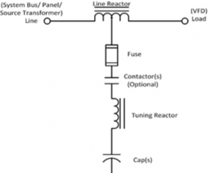
Figure 1: Simplified one-line of a passive harmonic filter.
Drive Impedance Considerations
Filter input iTHD
Passive filters are tuned to eliminate low order harmonics seen by the source, thereby decreasing the current THD to 5% or less when paired with a 6-pulse VFD. IEEE-519 requirements establish that when a system has an ISC/IL < 20, 5% iTHD at full load is the maximum allowed harmonic content. Chart 1 shows how TCI’s HGL and HGP filters compare to a leading ‘generator compatible’ filter from a competing manufacturer. Each test had the same 5% source impedance, the same 30 HP VFD with no impedance and an appropriately sized harmonic filter.
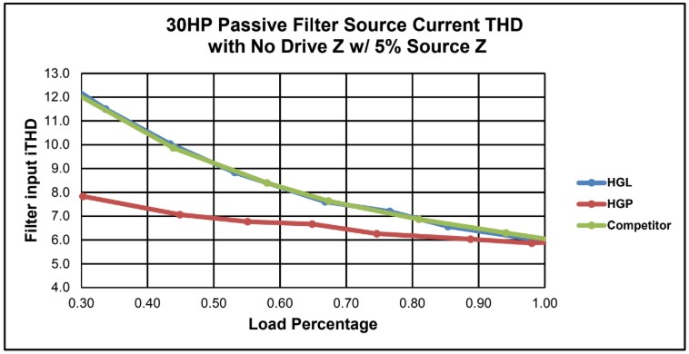
Figure 2
The graph (Figure 2) illustrates that with no drive impedance, none of the filters comply with the IEEE-519 5% iTHD requirement. Because of this, TCI recommends that all passive harmonic filters require drive impedance for proper operation.
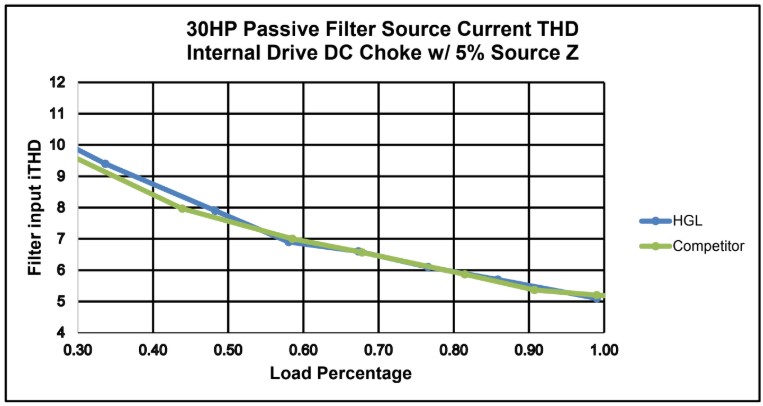
Figure 3
The graph (Figure 3) illustrates the performance of the HGL and the same “generator compatible” filter with a DC choke added to the VFD. This illustrates how the added impedance in the VFD can impact the filter’s ability to meet the IEEE-519 requirements.
Conclusions
Drive impedance must be considered when evaluating options to meet IEEE 519 compliance. TCI’s HGP and HGL filters are guaranteed to meet IEEE 519 when the minimum system requirements of drive impedance are satisfied.
For more information on how to size and select a passive filter, please reach out to our Technical Support team at 800-824-8282.
References
- “How to size a genset: Proper generator set sizing requires analysis of parameters and loads”, Cummins Power Topic #7007. https://www.cumminspower.com/www/literature/technicalpapers/PT-7007-Sizing-Gensets-en.pdf
- “Synchronous Generators and Leading Power Factor Loads”, ePower News, Fall 2011, Issue 2, Toromont CAT Power Systems. http://www.toromontcat.com/powersystems/pdf/newsletter/Synchronous%20Generators%20and%20Leading%20Power%20Factors.pdf
- “Impact of leading power factor loads on syn- chronous alternators”, Cummins Power Topic #6001. http://power.cummins.com/sites/default/files/literature/technicalpapers/PT-6001-ImpactofPowerFactor-Loads-en.pdf