HGA 5% Active Harmonic Filter

Elite System-Applied Harmonic Solution

The HarmonicGuard® Active (HGA) filter is an elite system-applied harmonic filter that minimizes harmonics to less than 5% total demand distortion (TDD) at the point of common coupling. The HGA monitors the load current and reacts to changes immediately. By injecting a counter-current, the active filter cancels out harmonics and synchronizes the current and voltage waveforms while improving power factor to near unity. One HGA filter can handle multiple non-linear, harmonic-generating loads.

Additionally, the HGA meets the demanding requirements of IEEE- 519-2022. Offering top of the line performance and mitigation, the HGA provides a lower cost and a smaller footprint than a comparable 18-pulse VFD or active front end drive.

A large, built-in 65k color touchscreen HMI display with LED backlight is included, along with communication options including Modbus RTU over RS485, EtherNet/IP, Modbus TCP/IP, BACNet/IP and DeviceNet.
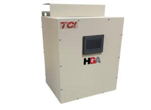
Maximized Harmonic Mitigation in a Minimized Space

TCI now manufactures the largest active harmonic filter in a single standalone enclosure, made in the USA. One 700 Amp HarmonicGuard Active (HGA) filter can correct harmonics for an entire system in excess of 2,000 HP of VFD load. The new 350 Amp size offers the highest harmonic current capacity to fit within a 30” MCC section.

Sizing an Active Filter

Sizing an active filter has many factors, including transformer size, amount of linear and non-linear load, and impedance in your drives. 

We understand sizing an Active filter can be difficult, which is why TCI created the HarmonicGuard Solution Center. It’s a completely free harmonic estimator software that enables users to size filtering solutions to meet harmonic calculations and power factor requirements.

The Harmonic Sizing Tool is a web-based software, no download necessary.

Features

  • Full range of active filters from 30-700 Amps
  • 208, 240, 480, and 600 VAC System Compatibility
  • Available in Open panel, Type 1, Type 12, and Type 3R
  • THID setpoint to ensure harmonic requirements are met 
  • Selectable harmonic correction from the 2nd to the 50th
  • Meets IEEE 519-2022 at all load levels as a system applied single filter solution.
  • cULus Listed; UL 508 Certified. No SCCR required by UL Standards for the filter.
  • Communication options: Modbus RTU over RS485, Modbus TCP/IP, EtherNet/IP, and BACNet/IP

Typical Applications

  • Fan Arrays
  • Chiller systems
  • Wastewater Treatment Plants
  • Industrial HVACR  & EC Motors
  • Multi-well Pads
  • Automation Production Facilities
  • Renewable Energy
  • Mining
  • Commercial Buildings
Unfiltered Waveform with Injection Current from the HGA
By actively monitoring the line or load current, the HGA harmonic filter determines the nature and quantity of harmonic currents in the system. It then cancels them by injecting equal amounts of harmonic currents opposite in phase. A state-of-the-art high speed DSP controller and a pulse width modulated (PWM) IGBT based power converter help to provide virtual real time compensation of non-linear load demanded by VFDs and other applications.
Resulting Line Current Waveform
with HGA
HGA also inherently tries to synchronize the line current with its voltage resulting in near unity displacement power factor. Thus, HGA provides solutions for both reactive current and harmonic current compensation.
Previous slide
Next slide

Current distortion limits for systems rated 120 V through 69 kV

Maximum harmonic current distortion in percent of IL
Individual harmonic order (odds harmonics) a,b

ISC/IL3≤h<1111≤h<1717≤h<2323≤h<3535≤h≤5050 TDD
<20c4.02.01.50.60.35.0
20<507.03.52.51.00.58.0
50<10010.04.54.01.50.712.0
100<100012.05.55.02.01.015.0
>100015.07.06.02.51.420.0
a. Even harmonics are limited to 25% of the odd harmonic limits above.
b. Current distortions that result in a dc offset, e.g., half-wave converters, are not allowed.
c. All power generation equipment is limited to these values of current distortion, regardless of actual ISC/IL.
where ISC = maximum short-circuit current at PCC.
and IL = maximum demand load current (fundamental frequency component) at the PCC under normal load operating conditions.

Quick Start

EnglishEspañolFrançaisHMI version on About screen
Version C
HMI Rev K
Version B
Version B
Version B
HMI Rev I
Version A
Version A
Version A
HMI Rev D – H

Legacy Manual

IOM EnglishHMI Version on About Screen
Version PHMI Rev A3-C6
Version OHMI Rev A2
Version NHMI Rev A1
Version MHMI Rev K
Version LHMI Rev K
Version KHMI Rev K
Version JHMI Rev K
Version HHMI Rev K
Version FHMI Rev J
Version EHMI Rev I
Version BHMI Rev D-H