Elite System-Applied Harmonic Solution
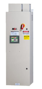
 The HarmonicGuard® Active (HGA) filter is an elite system-applied harmonic filter that minimizes harmonics to less than 5% total demand distortion (TDD) at the point of common coupling. The HGA monitors the load current and reacts to changes immediately. By injecting a counter-current, the active filter cancels out harmonics and synchronizes the current and voltage waveforms while improving power factor to near unity. One HGA filter can handle multiple non-linear, harmonic-generating loads.
Additionally, the HGA meets the demanding requirements of IEEE- 519-2022. Offering top of the line performance and mitigation, the HGA provides a lower cost and a smaller footprint than a comparable 18-pulse VFD or active front end drive.
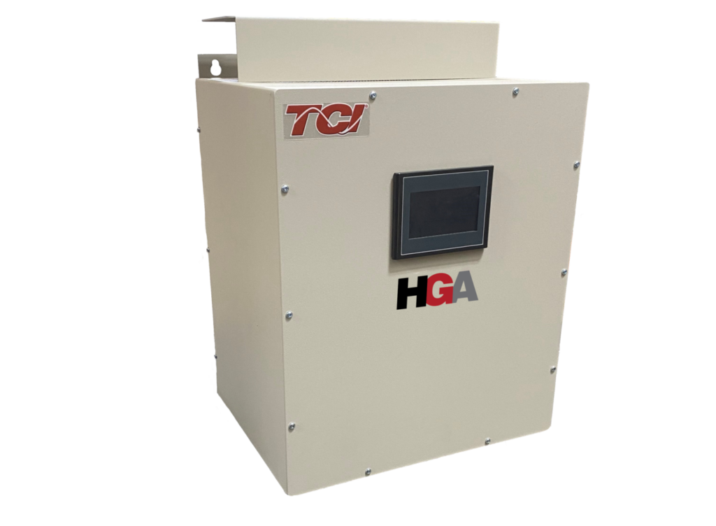
A large, built-in 65k color touchscreen HMI display with LED backlight is included, along with communication options including Modbus RTU over RS485, EtherNet/IP, Modbus TCP/IP, BACNet/IP and DeviceNet.
 Maximized Harmonic Mitigation in a Minimized Space

TCI is proud to announce our newest additions to the HGA HarmonicGuard Active Filter Line – the 30A and 50A filters. They allow for the smallest enclosure size yet – giving you harmonic compliance in the smallest of packages.
The new small filters are great for a variety of applications, including EC motors, fan arrays, wastewater treatment plants, chiller systems, multi-well pads, automation production facilities and so much more.
Sizing an Active Filter
Sizing an active filter has many factors, including transformer size, amount of linear and non-linear load, and impedance in your drives.
We understand sizing an Active filter can be difficult, which is why TCI created the HarmonicGuard Solution Center. It’s a completely free harmonic estimator software that enables users to size filtering solutions to meet harmonic calculations and power factor requirements.
The Harmonic Sizing Tool is a web-based software, no download necessary.
Features
- Full range of active filters from 30-700 Amps
- 208, 240, 480, and 600 VAC System Compatibility
- Available in Open panel, Type 1, Type 12, and Type 3R
- THID setpoint to ensure harmonic requirements are met
- Selectable harmonic correction from the 2nd to the 50th
- Meets IEEE 519-2022 at all load levels as a system applied single filter solution.
- cULus Listed; UL 508 Certified. No SCCR required by UL Standards for the filter.
- Communication options: Modbus RTU over RS485, Modbus TCP/IP, EtherNet/IP, and BACNet/IP
Typical Applications
- Fan Arrays
- Chiller systems
- Wastewater Treatment Plants
- Industrial HVACR & EC Motors
- Multi-well Pads
- Automation Production Facilities
- Renewable Energy
- Mining
- Commercial Buildings
with HGA
Current distortion limits for systems rated 120 V through 69 kV
Maximum harmonic current distortion in percent of IL
Individual harmonic order (odds harmonics) a,b
| ISC/IL | 3≤h<11 | 11≤h<17 | 17≤h<23 | 23≤h<35 | 35≤h≤50 | 50 TDD |
|---|---|---|---|---|---|---|
| <20c | 4.0 | 2.0 | 1.5 | 0.6 | 0.3 | 5.0 |
| 20<50 | 7.0 | 3.5 | 2.5 | 1.0 | 0.5 | 8.0 |
| 50<100 | 10.0 | 4.5 | 4.0 | 1.5 | 0.7 | 12.0 |
| 100<1000 | 12.0 | 5.5 | 5.0 | 2.0 | 1.0 | 15.0 |
| >1000 | 15.0 | 7.0 | 6.0 | 2.5 | 1.4 | 20.0 |
| a. Even harmonics are limited to 25% of the odd harmonic limits above. b. Current distortions that result in a dc offset, e.g., half-wave converters, are not allowed. c. All power generation equipment is limited to these values of current distortion, regardless of actual ISC/IL. |
||||||
| where ISC = maximum short-circuit current at PCC. and IL = maximum demand load current (fundamental frequency component) at the PCC under normal load operating conditions. |
||||||

